
VSWR vs Return Loss: One Is a Ratio. One Is a dB Value.
They both measure the same reflection problem in an RF system, but they speak two different mathematical languages. Here’s how to read each one, convert between them, and know which number actually matters for your project.
📅 Updated September 2026 · ⏱️ 14 min read · 🛠️ Reviewed by the ConvertersLab RF & Electronics team
If you’ve ever stared at an antenna datasheet and seen “VSWR 1.5:1” on one line and “Return Loss ≥ 14 dB” on another, and quietly wondered whether someone made a mistake, you’re not alone. Both numbers are describing the exact same physical event. Neither one is wrong. They’re just two different ways of reporting how much of your signal is bouncing back where it came from instead of doing useful work.
The confusing part is that these two numbers move in opposite directions. A lower VSWR is good. A higher return loss is good. Mix that up once during a design review and you’ll spend the next ten minutes explaining why you weren’t actually recommending a worse antenna. This guide sorts out exactly what each term means, how they’re calculated, and how to move between them without a calculator glued to your hand.
What’s in this guide
- What Is VSWR?
- What Is Return Loss?
- VSWR vs Return Loss: The Core Difference
- The Math That Connects Them
- VSWR to Return Loss Conversion Table
- How to Measure VSWR and Return Loss
- Which One Should You Actually Use?
- What Causes a High VSWR or Poor Return Loss
- How to Improve Your Numbers
- Frequently Asked Questions
What Is VSWR (Voltage Standing Wave Ratio)?
Picture a signal traveling down a coaxial cable toward an antenna. If the antenna’s impedance doesn’t exactly match the cable’s impedance, usually 50 ohms in most RF work, part of that signal reflects and travels back down the cable in the opposite direction. Now you have two waves moving through the same cable at the same time, one heading out and one heading back, and where they overlap, they interfere with each other.
That interference creates a pattern of high and low voltage points along the cable that don’t move, which is why it’s called a standing wave. VSWR is simply the ratio between the highest voltage point in that pattern and the lowest one.
A perfectly matched system has no reflection at all, so there’s no standing wave, and VSWR equals exactly 1.0, often written as 1:1. As the mismatch gets worse, more energy reflects, the standing wave pattern gets more pronounced, and the VSWR number climbs. A VSWR can never go below 1.0, and in the worst case, a completely open or shorted connection, it approaches infinity.
Reading the VSWR scale
| VSWR | What it means in practice |
|---|---|
| 1.0 : 1 | Perfect match. No reflected power. Purely theoretical outside a lab. |
| 1.2 : 1 | Excellent match, typical of a well-tuned antenna at its center frequency. |
| 1.5 : 1 | Very good, and the usual target spec for commercial and amateur antennas. |
| 2.0 : 1 | Acceptable working limit for most low-to-mid power systems. |
| 3.0 : 1 | Noticeably mismatched. Many transmitters will start folding back power. |
| > 5.0 : 1 | Poor match. Expect real signal loss and possible equipment stress. |
What Is Return Loss?
Return loss looks at the exact same reflection, but it measures it in terms of power instead of voltage, and it reports the result in decibels rather than a ratio. Specifically, it compares how much power you sent toward the load against how much power came bouncing back.
Here’s the part that trips people up: because return loss is built from a ratio of incident power to reflected power, a bigger number means less power is coming back. A return loss of 20 dB is a much better match than a return loss of 6 dB, even though 20 is the larger number. That’s the opposite direction from VSWR, where the smaller number is the better outcome.
Strictly speaking, the raw math on return loss produces a negative decibel value, since you’re describing a loss. By long-standing convention, engineers drop the negative sign and simply state return loss as a positive number, with the understanding that a higher value always means better performance.
Reading the return loss scale
| Return Loss | What it means in practice |
|---|---|
| 0 dB | Total reflection. Open circuit or dead short at the load. |
| 6 dB | Roughly a quarter of your power is bouncing back. Poor match. |
| 10 dB | About 90% of power reaches the load. Common minimum spec. |
| 14 dB | Around 96% delivered. Solid, typical antenna target. |
| 20 dB | Roughly 99% delivered. Excellent match. |
| ∞ dB | Perfect match, zero reflection. Theoretical only. |
VSWR vs Return Loss: The Core Difference
Both numbers describe impedance mismatch, and both come from the same underlying reflection coefficient. The difference is entirely in how the number behaves and what scale it lives on.
VSWR vs Return Loss at a glance
| Aspect | VSWR | Return Loss |
|---|---|---|
| Unit | Unitless ratio (e.g. 1.5:1) | Decibels (dB) |
| Best possible value | 1.0 | Infinite |
| Direction of "better" | Lower is better | Higher is better |
| Based on | Voltage (linear scale) | Power (logarithmic scale) |
| Common use case | Transmitter specs, ham radio, quick field checks | Antenna and RF component datasheets, VNA displays |
| Intuitive at a glance? | Yes, close to 1 is good | Needs the log scale to click first |
The Math That Connects Them
Both VSWR and return loss are downstream of a third quantity called the reflection coefficient, symbol Γ (gamma). This is the ratio of the reflected wave’s voltage to the incident wave’s voltage, and it’s the actual measurement a network analyzer takes at the S11 port.
Once you have Γ, you can get to either VSWR or return loss directly:
You can also skip Γ entirely and convert straight between VSWR and return loss:
None of this is complicated once you’ve done it two or three times by hand, but nobody wants to do it fifteen times in a row while comparing antenna options. That’s exactly the kind of repetitive conversion our VHF antenna calculator handles automatically, alongside VSWR and reflection coefficient outputs on the same page.
VSWR to Return Loss Conversion Table
Here’s a reference table covering the values you’ll run into most often in antenna and RF work, from a near-perfect match down to a badly mismatched load.
VSWR, return loss, reflection coefficient, and power reflected
| VSWR | Return Loss (dB) | Reflection Coeff. (Γ) | Power Reflected |
|---|---|---|---|
| 1.00 : 1 | ∞ | 0.000 | 0% |
| 1.10 : 1 | 26.4 dB | 0.048 | 0.2% |
| 1.20 : 1 | 20.8 dB | 0.091 | 0.8% |
| 1.50 : 1 | 14.0 dB | 0.200 | 4.0% |
| 2.00 : 1 | 9.5 dB | 0.333 | 11.1% |
| 2.50 : 1 | 7.4 dB | 0.429 | 18.4% |
| 3.00 : 1 | 6.0 dB | 0.500 | 25.0% |
| 5.00 : 1 | 3.5 dB | 0.667 | 44.4% |
| 10.00 : 1 | 1.7 dB | 0.818 | 66.9% |
| ∞ : 1 | 0 dB | 1.000 | 100% |
Worth pointing out, because the keyword shows up constantly in search: a 10 dB return loss corresponds to roughly a 1.92:1 VSWR, and a 14 dB return loss lines up almost exactly with the common 1.5:1 VSWR target. If a spec sheet gives you one number and your notes are in the other format, this table (or the calculator linked above) closes that gap in seconds.
How to Measure VSWR and Return Loss
Both values ultimately come from the same physical measurement, so the instrument doesn’t change, only the display mode does.
Vector Network Analyzer (VNA)
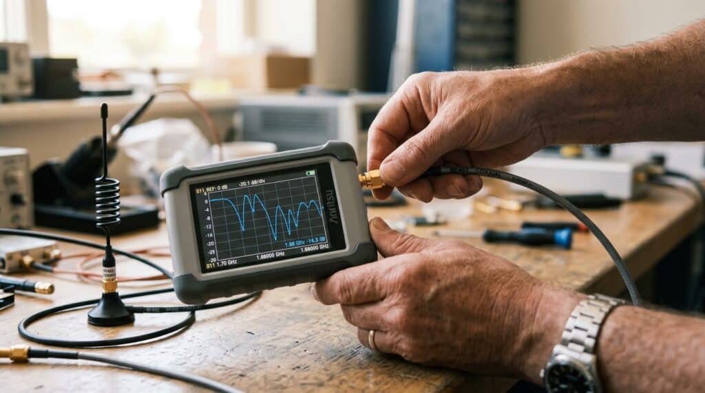
This is the standard tool for serious antenna and RF component work. A VNA sends a known signal into the device under test and measures both the magnitude and phase of what reflects back, which is the S11 parameter. Most VNAs let you toggle the display between return loss in dB, VSWR, or the raw Smith chart representation of Γ, all from the same sweep.
Directional Coupler and Power Meter
Before affordable VNAs were common, engineers measured forward and reflected power separately using a directional coupler feeding a power meter, then calculated VSWR or return loss from the ratio manually. It’s slower, but it still works fine for spot checks in the field.
Built-In Transmitter Meters
Many radio transmitters, especially in amateur radio, include an internal VSWR meter that gives a quick reading without any extra test gear. These are convenient but generally less precise than a proper VNA sweep across the full frequency band.

Which One Should You Actually Use?
In most day-to-day work, you don’t get to pick, whichever number your datasheet, transmitter, or client specifies is the one you use. But if you’re writing your own spec or deciding how to report a measurement, here’s how the two typically split by use case.
Typical usage by application
| Application | Number usually quoted | Why |
|---|---|---|
| Amateur radio transmitters | VSWR | Built into most radios' front-panel meters; simple to glance at |
| Antenna manufacturer datasheets | Return loss (and often VSWR alongside it) | Matches VNA output directly, easy to plot across frequency |
| Aerospace and defense cable testing | Return loss | dB scale fits naturally with other loss budgets in the link chain |
| 5G and cellular antenna specs | Both, side by side | Regulatory and industry documents often require both formats |
| RFID reader antennas | Return loss | Read range calculations are power-based, so dB fits the math directly |
| Radar systems | Return loss | Ties directly into overall link budget and power calculations |
Notice the pattern: whenever the surrounding math is already power-based, like link budgets, radar equations, or RFID range calculations, return loss slots in naturally because it’s already on a power scale. Whenever the context is a quick field check or a simple pass/fail glance, VSWR tends to win because 1.5 is easier to eyeball than 14 dB.
What Causes a High VSWR or Poor Return Loss
When a reading comes back worse than expected, the cause is almost always one of a handful of usual suspects.
- Connector problems. Corroded, loose, or improperly torqued connectors are the single most common cause of a sudden VSWR spike, especially after outdoor exposure.
- Damaged feedline. A kinked, crushed, or water-infiltrated coaxial cable changes its characteristic impedance along the damaged section, creating a mismatch that wasn’t there when it was installed.
- Antenna detuning. Nearby metal structures, ice buildup, or even wet foliage can shift an antenna’s resonant frequency enough to push VSWR outside its design range.
- Wrong antenna for the frequency. An antenna cut for one band will show a poor match if you try to drive it at a frequency it wasn’t designed for.
- Measurement error. Sometimes the antenna is fine and the problem is an uncalibrated VNA, a bad test cable, or measuring at the wrong reference plane.
How to Improve Your Numbers
Once you’ve identified the cause, the fix is usually one of these:
- Inspect and reseat connectors first. It’s the fastest check and the most frequent fix, so rule it out before assuming the antenna itself has failed.
- Sweep the full band, not just the center frequency. A narrow dip at one frequency with poor performance on either side usually points to a tuning issue rather than a hardware fault.
- Add an impedance matching network. When the antenna itself is fundamentally mismatched to your system impedance, a matching network (L-network, stub, or transformer) can bring VSWR down without changing the antenna.
- Check for physical obstructions. Move or trim anything metallic or wet that sits within a wavelength or two of the antenna element.
- Replace suspect feedline sections. If a cable shows a sudden impedance step along its length on a time-domain reflectometry sweep, that section needs replacing rather than patching.
Related tools on ConvertersLab
- VHF Antenna Calculator — dial in VSWR, return loss, and reflection coefficient together
- Fiber Optic Link Loss Calculator — for the optical side of a mixed RF/fiber signal chain
- dBm to Volts Converter — useful once you're translating reflected power into voltage terms
Frequently Asked Questions
What does VSWR stand for?
Voltage Standing Wave Ratio. It compares the highest voltage point on a transmission line to the lowest voltage point, which reveals how much signal is reflecting back toward the source instead of reaching the load.
What is return loss in simple terms?
It’s a decibel measurement of how much weaker the reflected signal is compared to what you sent out. A bigger return loss number means less energy is bouncing back, which is what you want.
Is VSWR the same as return loss?
They describe the same impedance mismatch, but they’re not the same measurement. VSWR is a unitless ratio that’s always 1.0 or higher, and return loss is a decibel value where a higher number means a better match.
Why is return loss written as a positive number if it's technically a loss?
The raw formula produces a negative dB figure, but by long-standing engineering convention the sign is dropped and return loss is reported as positive, since everyone already understands that a bigger number is better.
What is a good VSWR value for an antenna?
1.5:1 or lower is considered very good for most commercial and amateur setups, and 2:1 is often treated as the practical working limit. The right target really depends on your power budget and how sensitive your transmitter is to reflected power.
What return loss corresponds to a VSWR of 2:1?
About 9.5 dB, meaning roughly 11 percent of your forward power is reflecting back toward the source at that mismatch level.
How do I measure VSWR and return loss?
A vector network analyzer measuring the S11 parameter at the device port is the standard method. Most VNAs can display that one measurement as either return loss in dB or as a VSWR ratio.
What causes high VSWR in an antenna system?
Most often it’s a corroded or loose connector, a damaged feedline, an antenna that’s been detuned by nearby objects or weather, or simply the wrong antenna for the operating frequency.
Can return loss be too high?
No. A higher return loss always means a better match, with no practical upper limit. A theoretically perfect match would show infinite return loss and a VSWR of exactly 1.0.
The Bottom Line
VSWR and return loss aren’t competing measurements, they’re the same story told in two different units. VSWR gives you a simple ratio that’s easy to eyeball on a meter. Return loss gives you a decibel figure that slots naturally into a larger power budget. Once you know the conversion, and you can lean on the table above or our calculator whenever you need to move between them quickly, neither one should ever catch you off guard on a datasheet again.
The next time a spec sheet throws a VSWR figure at you and your notes are all in dB, you’ll know exactly what’s going on, and exactly what to do about it.
Further reading
- Return loss reference tables and derivation notes, Broadband Library
- Return loss and VSWR explained without heavy math, Antenna Test Lab
- Reading VSWR and return loss charts on antenna datasheets, Siretta
This guide is maintained by the ConvertersLab RF & Electronics team as part of our free calculator and reference library. Found an error or have a topic you'd like.