
EIRP Calculator: Why your 30 dBm radio is not 30 dBm EIRP
99.5% Helpful Guide for RF Engineers
If you’ve ever stared at a spec sheet and seen “EIRP: 36 dBm” and quietly wondered whether that’s a lot or a little — you’re not alone. Every Wi-Fi installer, ham radio operator, and wireless ISP technician runs into this term eventually, usually right when it matters most.
This guide walks through the formula, worked examples, the FCC and ETSI limits you’re actually expected to follow, and the mistakes that quietly get people non-compliant without them realizing it.
Equivalent Isotropically Radiated Power Calculator
Accurately evaluate total radiated radio frequency output power. Compute linear and logarithmic EIRP in real-time for Wi-Fi APs, cellular sites, outdoor Point-to-Point links, and IoT gateways.
RF Transmitter Inputs
Calculated EIRP
How to Use This Calculator
Follow these simple steps to calculate your system's effective radiated energy.
Input Transmit Power
Select your power unit (dBm, Watts, or mW) and enter the transmitter output rating from your radio datasheet.
Subtract Coaxial Line Loss
Enter total signal loss caused by coax cables, adapters, and surge suppressors between the radio and the antenna feed point in dB.
Add Antenna Gain
Specify the directional gain of your antenna in dBi. Real-time results update instantly in both dBm and linear power.
Calculation Formula & Mathematics
EIRP represents the total power that an isotropic antenna would radiate to produce the observed peak spatial power density.
Power Conversion Formulas:
• Watts to dBm: P(dBm) = 10 × log10(P(W) × 1000)
• dBm to Watts: P(W) = 10^((P(dBm) - 30) / 10)
Standard Regulatory EIRP Limits Reference
Maximum permitted EIRP varies by country and frequency band to prevent mutual spectrum interference.
| Band / Frequency | Authority | Application | Max Allowed EIRP |
|---|---|---|---|
| 2.4 GHz ISM | FCC (USA) | Point-to-Multipoint (Wi-Fi) | 36 dBm (4.0 W) |
| 2.4 GHz ISM | ETSI (Europe) | Wi-Fi / Bluetooth | 20 dBm (100 mW) |
| 5.150 – 5.250 GHz (UNII-1) | FCC (USA) | Indoor Wi-Fi APs | 30 dBm (1.0 W) |
| 5.725 – 5.850 GHz (UNII-3) | FCC (USA) | Fixed Point-to-Point Links | Unlimited (with 3:1 antenna scaling rule) |
| 868 MHz ISM | ETSI (Europe) | LoRaWAN / IoT Devices | 14 dBm (25 mW) |
Quick Answer
EIRP (Effective Isotropic Radiated Power) is the total power a transmitter appears to radiate in the direction of an antenna’s strongest gain, as if that power came from a theoretical isotropic antenna.
EIRP (dBm) = Transmit Power (dBm) − Cable/Connector Loss (dB) + Antenna Gain (dBi)
A Wi-Fi router putting out 20 dBm (100 mW), losing 1 dB to its cable, and feeding a 6 dBi antenna radiates an EIRP of 25 dBm (about 316 mW).
What Is EIRP (Effective Isotropic Radiated Power)?
Effective Isotropic Radiated Power is a way of describing how strong a radio signal effectively is in its strongest direction, accounting for everything between the transmitter and free space: the radio’s own output power, whatever it loses in cables and connectors along the way, and whatever it gains back from the antenna’s directionality.
The “isotropic” part is the key. An isotropic radiator is a theoretical antenna — it doesn’t exist in the real world — that radiates power perfectly evenly in every direction, like a bare lightbulb radiating light equally in a full sphere. Real antennas shape the signal, concentrating it into a lobe pointed where you want it instead of wasting it on the ceiling and the floor. EIRP tells you how strong the signal is in that concentrated direction, expressed as if an isotropic antenna had radiated it.
This matters for two audiences: regulators, who care about EIRP because it determines interference potential regardless of how the power got there, and engineers planning a link, who use EIRP as the starting point of every link budget.

The EIRP Formula (Simple Math, No Dread)
EIRP (dBm) = PTX (dBm) − Lcable (dB) + Gantenna (dBi)
| Symbol | Meaning | Typical Source |
|---|---|---|
| PTX | Transmitter output power at the radio's connector (“conducted power”) | Radio spec sheet, or measured with a power meter |
| Lcable | Total loss from all cables, connectors, and in-line components | Cable manufacturer's loss chart, by frequency and length |
| Gantenna | Antenna gain, in dBi | Antenna spec sheet |
| EIRP | Effective radiated power in the antenna's direction of maximum gain | This calculator |
Because decibels are logarithmic, you add and subtract dB values instead of multiplying — that’s the trick that makes this formula quick to run in your head once it’s familiar. Every 3 dB you add roughly doubles the power; every 3 dB you subtract roughly halves it.
If your antenna gain is given in dBd instead of dBi, convert it first — see the dBi vs. dBd section below.
How to Calculate EIRP Step-by-Step (Worked Examples)
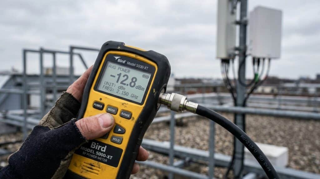
Example 1: Indoor Wi-Fi Access Point
- Transmit power: 20 dBm (100 mW)
- Cable/connector loss: 1 dB
- Antenna gain: 6 dBi
EIRP = 20 − 1 + 6 = 25 dBm ≈ 316 mW
Example 2: Outdoor Point-to-Point Wireless Bridge
- Transmit power: 27 dBm (500 mW)
- Cable/connector loss: 2 dB
- Antenna gain: 24 dBi (parabolic dish)
EIRP = 27 − 2 + 24 = 49 dBm ≈ 79 W
| Step | Example 1 (Indoor AP) | Example 2 (P2P Bridge) |
|---|---|---|
| 1. Start with conducted power (dBm) | 20 dBm | 27 dBm |
| 2. Subtract cable/connector loss | −1 dB | −2 dB |
| 3. Add antenna gain (dBi) | +6 dBi | +24 dBi |
| Result: EIRP | 25 dBm (≈316 mW) | 49 dBm (≈79 W) |
EIRP vs. ERP: The 2.15 dB Difference Every RF Engineer Must Know
EIRP and ERP (Effective Radiated Power) both describe how strong a signal is in an antenna’s strongest direction — the difference is only in the reference antenna each one uses.
- EIRP references an isotropic radiator (0 dBi gain by definition).
- ERP references a half-wave dipole antenna, which already has 2.15 dB of gain over an isotropic radiator.
That 2.15 dB gap flows straight into antenna gain units too: dBi (gain over isotropic) and dBd (gain over a dipole) describe the same antenna differently, with dBi always reading 2.15 higher than dBd for that same antenna.
| Antenna Gain | In dBd | In dBi | EIRP if Fed 100 mW (20 dBm), No Cable Loss |
|---|---|---|---|
| Reference dipole | 0 dBd | 2.15 dBi | 22.15 dBm |
| Common Wi-Fi antenna | 3.85 dBd | 6 dBi | 26 dBm |
| Mid-gain panel | 6.85 dBd | 9 dBi | 29 dBm |
| High-gain panel | 9.85 dBd | 12 dBi | 32 dBm |
| Small dish | 20.85 dBd | 23 dBi | 43 dBm |
Conversion formulas: dBi = dBd + 2.15 • dBd = dBi − 2.15
To convert ERP to EIRP: EIRP (dBm) = ERP (dBm) + 2.15. To convert EIRP to ERP: ERP (dBm) = EIRP (dBm) − 2.15.
Understanding the Calculator's Three Inputs
Transmit power (conducted power). The power measured right at the radio’s antenna connector — before the cable, before the antenna. Don’t confuse this with a radio’s “max output” marketing spec, which sometimes bakes in antenna-gain assumptions.
Cable and connector loss. Every foot of coax, every connector, every lightning arrestor or splitter eats a small amount of signal — and it adds up faster than most people expect. 3 dB is half your power, gone before it reaches the antenna.
Antenna gain. This is where the antenna concentrates power instead of spreading it evenly, and it’s usually the single biggest number in the equation. Always confirm the unit (dBi vs. dBd) before using it.
Conducted power vs. radiated power, in plain terms: conducted power is what goes into the antenna; radiated (effective) power is what comes out, in the antenna’s favored direction, after cable losses and antenna gain have both had their say.
FCC EIRP Limits: What US Deployments Must Follow
The FCC regulates EIRP under Part 15 for unlicensed devices, and the rules differ by band, by whether the link is point-to-multipoint or point-to-point, and by antenna gain — treat the table below as an orientation, not a substitute for checking the current rule text.
| Band | Deployment Type | Typical Rule (Part 15.247 / 15.407) |
|---|---|---|
| 2.4 GHz (2400–2483.5 MHz) | Point-to-multipoint | Conducted power up to 1 W (30 dBm) with up to 6 dBi antenna gain, giving max EIRP 36 dBm (4 W); above 6 dBi, conducted power is reduced roughly 1 dB per 1 dB of added gain |
| 2.4 GHz | Fixed point-to-point | A separate rule reduces conducted power more gradually (≈1 dB per 3 dB of gain above 6 dBi), allowing EIRP to climb meaningfully above 36 dBm |
| 5.8 GHz (UNII-3, 5725–5850 MHz) | Fixed point-to-point | Directional antennas up to 23 dBi with no conducted-power reduction; historically permits EIRP up into the 50+ dBm range for genuinely fixed links |
| 6 GHz (5925–7125 MHz) | Low-power indoor / standard power (AFC) | Governed by a newer, more complex framework (Part 15.407) — check the current rule text directly |
Do not treat the table above as a design limit without checking 47 CFR § 15.247 and 47 CFR § 15.407 directly. Antenna-gain provisions, point-to-point exceptions, and the 6 GHz framework all carry specific conditions a summary table can’t fully capture.
ETSI EIRP Limits: What European Deployments Must Follow
In the EU/UK, the relevant harmonized standards are ETSI EN 300 328 (2.4 GHz) and EN 301 893 (5 GHz), both tied to compliance with the Radio Equipment Directive.
| Band | Standard | Typical EIRP Limit |
|---|---|---|
| 2.4 GHz ISM (2400–2483.5 MHz) | EN 300 328 | 20 dBm (100 mW) max |
| 5.15–5.35 GHz (indoor only) | EN 301 893 | 23 dBm (200 mW) max, indoor only |
| 5.47–5.725 GHz | EN 301 893 | 30 dBm (1 W) max, indoor/outdoor, DFS + TPC required |
| 5.725–5.850 GHz | EN 301 893 (V2.2.1+) | Now within EN 301 893 scope — check the version applicable to your product |
The pattern to notice: Europe’s 2.4 GHz limit (20 dBm) is significantly stricter than the FCC’s (36 dBm) — a device compliant in the US at full power is often not compliant in Europe without a power reduction, which is exactly why enterprise access points offer a country/regulatory-domain setting.
EIRP Calculator by Band: Wi-Fi, 5G, LoRa, Satellite, and Microwave
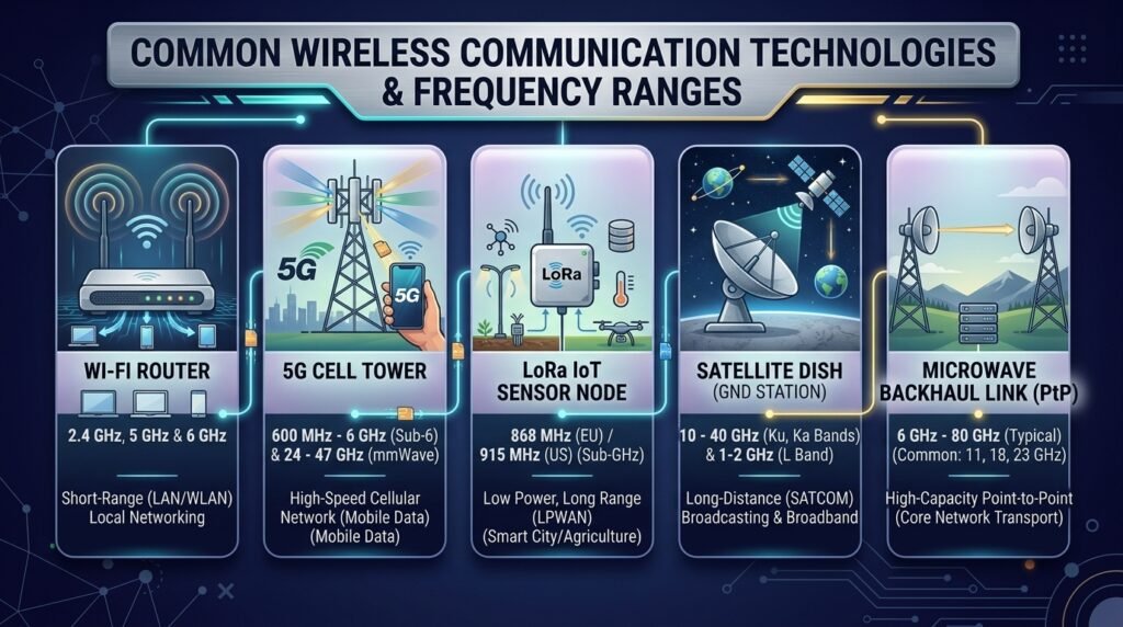
- Wi-Fi (2.4/5/6 GHz): Governed by Part 15.247/15.407 (US) and EN 300 328/301 893 (Europe). Outdoor point-to-point bridges are where EIRP calculations matter most for compliance.
- 5G NR (sub-6 GHz and mmWave): Licensed deployments follow carrier-specific, licensed-band power rules — but the same EIRP math still applies underneath, and mmWave systems lean heavily on antenna gain and beamforming to overcome much higher path loss.
- LoRa/IoT (900 MHz): Typically governed by Part 15.247 (US, 902–928 MHz) or short-range-device rules in Europe; limits tend to be generous since conducted power starts very low.
- Satellite uplink: EIRP is a headline spec here, often expressed in dBW, because satellite links operate on razor-thin margins.
- Microwave backhaul: High-gain dish antennas maximize EIRP within a narrow beam, which is why regulators carve out more generous allowances for fixed point-to-point links.
EIRP and Link Budget: How They Work Together
EIRP is the starting number in every wireless link budget — it’s the “how strong does this signal leave the transmitter” side of the equation. From there, a link budget calculator subtracts free space path loss (and any additional fade margin) to determine whether the signal will still be usable once it reaches the receiver’s antenna. If you’re planning an actual link rather than just checking compliance, pair this EIRP number with a free space path loss calculator to see what actually arrives at the far end.
MIMO, Beamforming, and EIRP: A Quick Look at Advanced Cases
Modern Wi-Fi and 5G systems complicate the simple EIRP formula slightly, because they can use multiple antenna elements and beamforming to shape and steer gain dynamically rather than relying on one fixed antenna’s published gain figure.
As one real-world example regulatory engineers use to illustrate this: a 4-element beamforming array, where each element has 11.8 dBi gain, produces an effective directional gain of roughly 17.8 dBi (element gain plus 10·log₁₀(4) for the 4 elements). Under FCC rules that require reducing conducted power as directional gain rises past 6 dBi, that might cap conducted output around 26.2 dBm — which, combined with the 17.8 dBi directional gain, still nets an EIRP around 44 dBm. Beamforming systems can reach high EIRP values even while each individual radio chain stays modest.
Common EIRP Mistakes (and How to Avoid Them)

| Mistake | Why It Happens | How to Avoid It |
|---|---|---|
| Mixing up dBi and dBd | Manufacturers publish dBi (bigger number); older references use dBd | Confirm the unit before using it; convert with dBi = dBd + 2.15 |
| Forgetting cable loss entirely | Feels like a “small” number next to antenna gain | Run an actual coax loss calculation for your cable type, length, and frequency |
| Using “max power” marketing specs instead of conducted power | Consumer spec sheets sometimes assume a specific antenna | Use conducted power measured at the radio's connector |
| Applying point-to-multipoint limits to a point-to-point link (or vice versa) | FCC/ETSI treat these differently, and it's easy to overlook | Confirm which deployment category your link falls under |
| Ignoring regional differences (US vs. EU) | A device legal in the US can silently exceed EU limits | Set the correct regulatory domain and re-check EIRP for your region |
| Forgetting duty cycle / aggregate power on multi-radio systems | MIMO/beamforming combines multiple chains | Calculate directional gain for the full array, not one element |
Frequently Asked Questions
Final Thoughts
EIRP looks intimidating mostly because of the acronym soup around it. Strip that away and it’s one formula with three inputs you can usually read straight off a spec sheet. The parts worth double-checking every time are the unit conversions (dBi vs. dBd) and which regulatory limit actually applies to your band, region, and deployment type.
Run your numbers through the calculator above, then cross-check the result against the FCC or ETSI table for your exact situation before you deploy.
Related Calculators on SmartTeleNet
Publish these internal links once each companion page is live — do not link to URLs that don’t exist yet.
- Coax Cable Loss Calculator — anchor text: “calculate your exact cable loss” →
/coax-cable-loss-calculator/ - dBi to dBd Antenna Gain Converter — anchor text: “convert between dBi and dBd” →
/dbi-to-dbd-calculator/ - Free Space Path Loss / Link Budget Calculator — anchor text: “run a full link budget” →
/free-space-path-loss-calculator/ - VSWR Calculator — anchor text: “check your antenna’s VSWR” →
/vswr-calculator/ - dBm to Watts Converter — anchor text: “convert dBm to watts” →
/dbm-to-watts-calculator/
External Sources Referenced
- 47 CFR § 15.247 — eCFR — FCC rules for the 902–928 MHz, 2.4 GHz, and 5.8 GHz unlicensed bands
- 47 CFR § 15.407 — Cornell Legal Information Institute — FCC general technical requirements including 6 GHz provisions
About the Author
Written by Jaweed — a retired electronics engineer based in Karachi, Pakistan, holding a Diploma in Electronics from the Government College of Technology (S.I.T.E., Karachi) and a Bachelor’s in Computer Science from Shah Abdul Latif University, Khairpur. Jaweed builds SEO-focused calculator tools and technical explainer content, drawing on a background in electronics engineering to keep the math and regulatory detail accurate.